如何理解SVPWM调制过程中的电压利用率?
来源: 电子工程世界
新闻行业新闻
对于一个特定的永磁电机驱动系统,其最大转速受反电动势的制约,转速越高需要越高的调制电压去平衡。因此,永磁电机需要充分利用DC侧的电压,以提高电机的转速性能。
关于电压利用率电机工程师和电控工程师的理解往往是不太一样的!
本文基于双极性PWM调制,Y型接法,讨论了各种调制电压的关系,希望做电机的小伙伴能够和做控制器的小伙伴达成共识。
1、对于电机线电压,在调制过程中两线之间电压有三种电压状态,+DC,0,-DC,线电压的最大调制出正弦电压的峰值为Udc,转化为相电压为Udc/sqrt(3)
2、在Y型接法的定子线圈中,线圈电压为2/3Udc, 1/3Udc, -1/3Udc, -2/3Udc, 中性点电压(参考DC侧GND)为1/3Udc,2/3Udc跳变,因此最大调制电压的峰值为2/3Udc
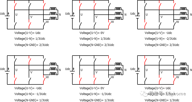
逆变器开关六状态
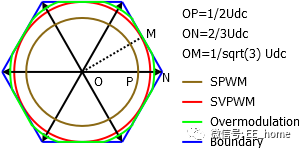
3、通过下面矢量图可以看出,内接圆是能够调制出正弦电压的最大圆,半径为sqrt(3)/2 *2/3Udc =Udc/sqrt(3) 和电机端相电压相等
4、超过该最大电压利用率,调制轨迹会在沿着六边形运动,形成“过调制”,此时基波电压增加,同时高次谐波分量增加。
5、控制器能够控制的最大电压边界为正六边形的边界,相电压基波电压为2/3Udc, 进入方波控制。
电压调制度
结论:电机端电压利用率为1等于相电压调制最大内接圆,相电压为Udc/sqrt(3);如果以最大调制电压为1/2Udc SPWM调制方式为基准,那么电压为2/ sqrt(3) * 1/2Udc, 也即是获得1.15倍SPWM最大调制电压。
文章来源于: 电子工程世界原文链接
本站所有转载文章系出于传递更多信息之目的,且明确注明来源,不希望被转载的媒体或个人可与我们联系,我们将立即进行删除处理。