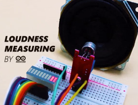
如何在Arduino中使用KY-037声音检测传感器
这个项目将教你如何在 Arduino 中使用 KY-037 声音检测传感器,并且测量环境中声音强度的变化。
能够学到什么
KY-037声音检测传感器介绍
KY-037声音检测模块如何配合Arduino使用
KY-037声音检测传感器
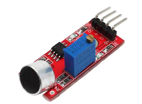
该模块由一个用于检测声音的灵敏电容麦克风和一个放大电路组成。该模块的输出是模拟和数字的。数字输出作为一个键,当声音强度达到一定阈值时激活。灵敏度阈值可以通过传感器上的电位器进行调整。
模拟输出电压随麦克风接收到的声音强度而变化。您可以将此输出连接到 Arduino 模拟引脚并处理输出电压。
将 KY-037 声音检测模块与 Arduino 连接
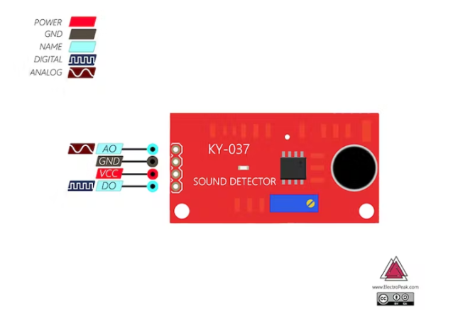
要将此模块与 Arduino 一起使用,只需连接模块的电源电压,然后根据需要将其模拟或数字引脚连接到 Arduino。
这里我们使用模拟输出。
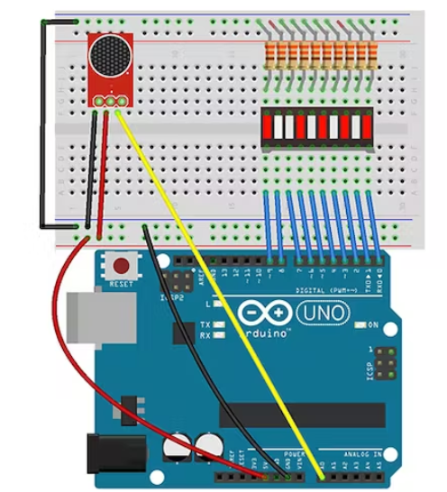
电路
如下图将传感器连接到 Arduino
代码
连接电路后,请执行以下步骤:
第 1 步:在您的 Arduino 板上上传以下代码:
void setup() {
Serial.begin(9600); // setup serial
}
void loop() {
Serial.println(analogRead(A0));
delay(100);
}
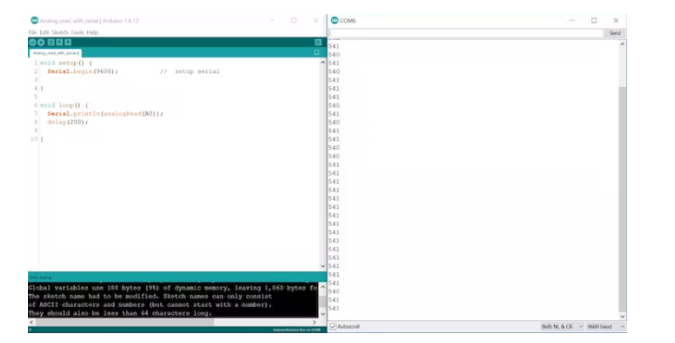
第 2 步:打开串行监视器窗口
现在转动电位器以关闭数字输出上的 LED。在 LED 熄灭后立即记下串行监视器中显示的数字。
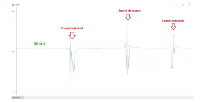
在图表上显示传感器的模拟输出
将传感器的模拟输出连接到 Arduino A0 引脚并在您的 Arduino 板上上传以下代码。然后从工具菜单中选择串行绘图仪。
第 3 步:在以下代码中写下您之前记下的数字(作为阈值变量)并将代码上传到您的板上。
/*
KY-037 Sound Detection Sensor + Arduino
modified on 16 Apr 2019
by Mohammadreza Akbari @ Electropeak
https://electropeak.com/learn/
*/
int sensor_value = 0;
int threshold = 540; //Enter Your threshold value here
int abs_value = 0;
int ledCount = 10; //number of Bargraph LEDs
int bargraph[] = {0, 1, 2, 3, 4, 5, 6, 7, 8, 9}; // Bargraph pins
void setup() {
Serial.begin(9600); // setup serial
for (int i = 0; i <= ledCount; i++) // Define bargraph pins OUTPUT
{
pinMode(bargraph[i], OUTPUT);
}
for (int i = 0; i <= 9; i++)
{
digitalWrite(i, LOW);
}
}
void loop() {
sensor_value = analogRead(A0);
abs_value = abs(sensor_value - threshold);
int ledLevel = map(abs_value, 0, (1024 - threshold), 0, ledCount);
for (int i = 0; i < ledCount; i++) {
// if the array element's index is less than ledLevel,
// turn the pin for this element on:
if (i < ledLevel) {
digitalWrite(bargraph[i], HIGH);
Serial.println(i);
}
// turn off all pins higher than the ledLevel:
else {
digitalWrite(bargraph[i], LOW);
}
}
}
未来可能的拓展
当声音达到特定阈值时,设备开始自动存储声音。(可以使用VS1053等模块来存储音频。)
传感器部分:
/*
KY-037 Sound Detection Sensor + Arduino
modified on 16 Apr 2019
by Mohammadreza Akbari @ Electropeak
https://electropeak.com/learn/
*/
int sensor_value = 0;
int threshold = 540; //Enter Your threshold value here
int abs_value = 0;
int ledCount = 10; //number of Bargraph LEDs
int bargraph[] = {0, 1, 2, 3, 4, 5, 6, 7, 8, 9}; // Bargraph pins
void setup() {
Serial.begin(9600); // setup serial
for (int i = 0; i <= ledCount; i++) // Define bargraph pins OUTPUT
{
pinMode(bargraph[i], OUTPUT);
}
for (int i = 0; i <= 9; i++)
{
digitalWrite(i, LOW);
}
}
void loop() {
sensor_value = analogRead(A0);
abs_value = abs(sensor_value - threshold);
int ledLevel = map(abs_value, 0, (1024 - threshold), 0, ledCount);
for (int i = 0; i < ledCount; i++) {
// if the array element's index is less than ledLevel,
// turn the pin for this element on:
if (i < ledLevel) {
digitalWrite(bargraph[i], HIGH);
Serial.println(i);
}
// turn off all pins higher than the ledLevel:
else {
digitalWrite(bargraph[i], LOW);
}
}
}
本站所有转载文章系出于传递更多信息之目的,且明确注明来源,不希望被转载的媒体或个人可与我们联系,我们将立即进行删除处理。