基于STM32的元器件特性测试仪过程
元器件特性测试仪任务要求
通过编程完成对5种以上元器件特性的测量
能够自动识别元器件
在OLED屏幕上通过图形化的界面显示各种元器件的符号及测量得到的信息
实验环境
硬件:STM32G031G8U6核心板、硬禾学堂制作的底板
软件:STM32CubeMX、CLion、STM32CubeProgrammer
实现思路
首先进行一个大致的元器件类型的判断,再精确地测量元器件的各项属性,最后显示在OLED屏幕上
各部分的介绍元器件类型的判断
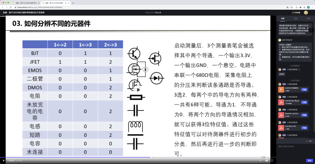
思路:首先给元器件放电,再轮番给这3pin中的每2pin进行正反地通电,会得到六次结果。将每2pin的结果存储下来,进行排序后根据元器件特性进行判断元器件的类型,初步判断后存下引脚信息并进行参数的测量和屏幕显示,具体参考如图:
代码如下
void QuickCheck() {
QUICKJUDGE result = {0}; //before compare, the result.sat should be sorted
uint8_t BJTFEA[4] = “011”; //BJT
uint8_t DioFea[4] = “001”; //diode/E-MOS
uint8_t ResFea[4] = “002”; //resistance/inductance/charged capacitance
uint8_t CapFea[4] = “000”; //capacitance/no element
uint8_t temp; //交换时用于缓存变量
discharge();
if (QuickTestBetween2Pin(MiddlePort, HighPort, LowPort))
result.Bmh = 1;
/* 共六组测量,代码省略 */
discharge();
if (QuickTestBetween2Pin(LowPort, HighPort, MiddlePort))
result.Blh = 1;
result.Sta[0] = result.Bmh + result.Bhm + ‘0’;
result.Sta[1] = result.Bml + result.Blm + ‘0’;
result.Sta[2] = result.Bhl + result.Blh + ‘0’;
/// Sort the result.sta from little to big
if (result.Sta[0] 》 result.Sta[1])
temp = result.Sta[0], result.Sta[0] = result.Sta[1], result.Sta[1] = temp;
if (result.Sta[1] 》 result.Sta[2])
temp = result.Sta[1], result.Sta[1] = result.Sta[2], result.Sta[2] = temp;
if (result.Sta[0] 》 result.Sta[2])
temp = result.Sta[0], result.Sta[0] = result.Sta[2], result.Sta[2] = temp;
result.Sta[3] = ‘’;
/// 以下是逐个判断元器件特征是否和已知特征符合
if (strcmp(result.Sta, CapFea) == 0) {
if (IsCap_Check()) {
ComponentFound = COMPONENT_CAPACITANCE;
Capacitance_Check(*ComponentParam.CAPPARAM.front, *ComponentParam.CAPPARAM.rear);
Capacitance_Display(ComponentParam);
} else {
Error_Report();
}
} else if (strcmp(result.Sta, DioFea) == 0) {
//TODO:Add emos and diode check
//TODO:Sometimes the caps may be metered as a diode
ComponentFound = COMPONENT_DIODE;
if (result.Bml + result.Blm) {
ComponentParam.DiodeParam.front = &MiddlePort;
ComponentParam.DiodeParam.rear = &LowPort;
} else if (result.Bhm + result.Bmh) {
ComponentParam.DiodeParam.front = &MiddlePort;
ComponentParam.DiodeParam.rear = &HighPort;
} else if (result.Blh + result.Bhl) {
ComponentParam.DiodeParam.front = &LowPort;
ComponentParam.DiodeParam.rear = &HighPort;
}
Diode_Check(*ComponentParam.DiodeParam.front, *ComponentParam.DiodeParam.rear);
Diode_Display(ComponentParam);
} else if (strcmp(result.Sta, ResFea) == 0) {
uint8_t ret = 0;
if (result.Bml + result.Blm) {
ret = IsIndOrRes_Check_Between2Pin(MiddlePort, LowPort, HighPort);
ComponentParam.RESPARAM.front = &MiddlePort;
ComponentParam.RESPARAM.rear = &LowPort;
ComponentParam.INDPARAM.front = &MiddlePort;
ComponentParam.INDPARAM.rear = &LowPort;
} else if (result.Bhm + result.Bmh) {
ret = IsIndOrRes_Check_Between2Pin(HighPort, MiddlePort, LowPort);
ComponentParam.RESPARAM.front = &MiddlePort;
ComponentParam.RESPARAM.rear = &HighPort;
ComponentParam.INDPARAM.front = &MiddlePort;
ComponentParam.INDPARAM.rear = &HighPort;
} else if (result.Blh + result.Bhl) {
ret = IsIndOrRes_Check_Between2Pin(LowPort, HighPort, MiddlePort);
ComponentParam.RESPARAM.front = &LowPort;
ComponentParam.RESPARAM.rear = &HighPort;
ComponentParam.INDPARAM.front = &LowPort;
ComponentParam.INDPARAM.rear = &HighPort;
}
if (ret == 1) {
Inductance_Check(*ComponentParam.INDPARAM.front, *ComponentParam.INDPARAM.rear);
Inductance_Display(ComponentParam);
} else if (ret == 2) {
Resistance_Check(*ComponentParam.RESPARAM.front, *ComponentParam.RESPARAM.rear);
Resistance_Display(ComponentParam);
} else {
Error_Report();
}
} else if (strcmp(result.Sta, BJTFEA) == 0) {
ComponentFound = COMPONENT_BJT;
if (result.Bhm + result.Bmh) {
ComponentParam.BJTPARAM.b = &LowPort;
ComponentParam.BJTPARAM.Channel = result.Blm;
} else if (result.Blm + result.Bml) {
ComponentParam.BJTPARAM.b = &HighPort;
ComponentParam.BJTPARAM.Channel = result.Bhl;
} else {
ComponentParam.BJTPARAM.b = &MiddlePort;
ComponentParam.BJTPARAM.Channel = result.Bmh;
}
BJT_Check();
BJT_Display(ComponentParam);
} else {
Error_Report();
}
discharge();
}
区分电阻和电感
可以给元器件充电后断电,如果检测到下端不为低电平,那就是电感。具体代码如下
/**
* @brief check the element is a inductance or a resistance
* @note firstly,set the fromPin to High and set the toPin to low
* the current direction will like that and the ADC will set here:
* fromPin---element---680r---toPin
* VCC ADC1 GND
* secondly,set the fromPin to Low and set a 470k to protect the io
* the current direction will like that and the ADC will set here:
* fromPin---470k---element---680r---toPin
* GND ADC2 GND
* if it is a inductance the ADC1 and the ADC2 will get a voltage
* while if it is a resistance the ADC1 will get a voltage and the ADC2 will be GND
* @param fromPort
* @param toPort
* @param unusedPort
* @return return 0 if it is no element ,
* return 1 if it is a inductance and
* return 2 if it is a resistance
*/
uint8_t IsIndOrRes_Check_Between2Pin(MEASUREPORT fromPort, MEASUREPORT toPort, MEASUREPORT unusedPort) {
uint16_t adcVol1, adcVol2;
MeasurePort_Init(fromPort, PORT_WITH_NONE, GPIO_PIN_SET);
MeasurePort_Init(toPort, PORT_WITH_680, GPIO_PIN_RESET);
MeasurePort_Init(unusedPort, PORT_FLOATING, GPIO_PIN_RESET);
HAL_GPIO_ReInit(toPort.PIN_WITH_NONE.GPIOx, toPort.PIN_WITH_NONE.GPIO_Pin, GPIO_MODE_ANALOG);
adcVol1 = GetVol(toPort);
MeasurePort_Init(fromPort, PORT_WITH_470K, GPIO_PIN_RESET);
adcVol2 = GetVol(toPort);
if ((adcVol1 《 ADCZERO) && (adcVol2 《 ADCZERO)) {
return 0;
} else if (adcVol2 《 ADCZERO) {
ComponentParam.INDPARAM.front = &fromPort;
ComponentParam.INDPARAM.rear = &toPort;
return 2;
} else {
ComponentParam.RESPARAM.front = &fromPort;
ComponentParam.RESPARAM.rear = &toPort;
return 1;
}
}
电阻的测量
电阻的参数主要有电阻值,可通过分压法测量。
首先使用680r电阻,电阻接在上端和下端各测试一次,并计算电阻值。如果电阻阻值过大,可以换用470k电阻。代码如下
/**
* @brief measure the value of resistance
* @note first measure will set as follows:
* FrontPort---resistance---680r---RearPort
* GND ADC VCC
* second measure will set as follows:
* FrontPort---680r---resistance---RearPormt
* GND ADC VCC
* third and forth measure will use the 470k resistance
* to instead the 680r to have a more accurate value
* when the resistance is big.
* @param FrontPort
* @param RearPort
*/
//TODO:the resistance of the ADC may cause some deviations when use the 470k resistance
void Resistance_Check(MEASUREPORT FrontPort, MEASUREPORT RearPort) {
uint16_t adcget[4];
float res[4];
MEASUREPORT unusedPort = GetUnusedPort(&FrontPort, &RearPort);
/// MeasurePort_Init函数用于重新初始化一个pin上的3个引脚至指定电阻和电平。
/// 如使用680r电阻,重新初始化其他两个引脚为浮空高阻,将连接着680r电阻的引脚设为指定电平
MeasurePort_Init(FrontPort, PORT_WITH_NONE, GPIO_PIN_RESET);
MeasurePort_Init(RearPort, PORT_WITH_680, GPIO_PIN_SET);
MeasurePort_Init(unusedPort, PORT_FLOATING, GPIO_PIN_RESET);
/// 重新初始化ADC引脚。ADC引脚一般为提供电阻的那组引脚中未接电阻的引脚
HAL_GPIO_ReInit(RearPort.PIN_WITH_NONE.GPIOx, RearPort.PIN_WITH_NONE.GPIO_Pin, GPIO_MODE_ANALOG);
/// GetVol函数用于测量指定引脚组中未接电阻那个引脚的电压
adcget[0] = GetVol(RearPort);
res[0] = 680 / (3300.0 / adcget[0] - 1);
MeasurePort_Init(FrontPort, PORT_WITH_680, GPIO_PIN_RESET);
MeasurePort_Init(RearPort, PORT_WITH_NONE, GPIO_PIN_SET);
MeasurePort_Init(unusedPort, PORT_FLOATING, GPIO_PIN_RESET);
HAL_GPIO_ReInit(FrontPort.PIN_WITH_NONE.GPIOx, FrontPort.PIN_WITH_NONE.GPIO_Pin, GPIO_MODE_ANALOG);
adcget[1] = GetVol(FrontPort);
res[1] = 680 / (adcget[1] / 3300.0) - 680;
if ((res[0] + res[1]) 》 1000) {
/* 与上面的代码类似,仅将680R改为470K电阻,省略 */
}
if ((res[0] + res[1]) 《= 10000) {
ComponentParam.RESPARAM.ResVal = (uint32_t) (res[0] + res[1]) / 2;
} else if ((res[0] + res[1]) 《= 1000000) {
qsort(res, 4, sizeof(float), cmpfunc);
ComponentParam.RESPARAM.ResVal = (uint32_t) (res[1] + res[2]) / 2;
} else {
ComponentParam.RESPARAM.ResVal = (uint32_t) (res[2] + res[3]) / 2;
}
}
电感的测量
电感的测量可以通过充电后测量放电时间来大致计算出电感值
/**
* @brief charge the inductance and discharge it
* @note get the discharge time and then calculate the value of the inductance
* the current direction will like that and the ADC will set here:
* FrontPort---680r---inductance---RearPort
* VCC ADC GND
* after charge, set the FrontPort to low
* the current direction will like that and the ADC will set here:
* FrontPort---680r---inductance---RearPort
* GND ADC GND
* if the discharge speed is too fast, use the 470k to instead and test again.
* @note calculating the value of the inductance is not verified
* @param FrontPort
* @param RearPort
*/
void Inductance_Check(MEASUREPORT FrontPort, MEASUREPORT RearPort) {
uint16_t adcget1, adcget2;
uint16_t time1, time2;
uint16_t i = 0;
MEASUREPORT unusedPort = GetUnusedPort(&FrontPort, &RearPort);
MeasurePort_Init(FrontPort, PORT_WITH_680, GPIO_PIN_SET);
MeasurePort_Init(RearPort, PORT_WITH_NONE, GPIO_PIN_RESET);
MeasurePort_Init(unusedPort, PORT_FLOATING, GPIO_PIN_RESET);
HAL_GPIO_ReInit(FrontPort.PIN_WITH_NONE.GPIOx, FrontPort.PIN_WITH_NONE.GPIO_Pin, GPIO_MODE_ANALOG);
HAL_Delay(100);
adcget1 = GetVol(FrontPort);
MeasurePort_Init(FrontPort, PORT_WITH_680, GPIO_PIN_RESET);
HAL_GPIO_ReInit(FrontPort.PIN_WITH_NONE.GPIOx, FrontPort.PIN_WITH_NONE.GPIO_Pin, GPIO_MODE_ANALOG);
time1 = HAL_GetTick();
while (i 《 0xffff) {
adcget2 = GetVol(FrontPort);
i++;
if (adcget2 《 ADCZERO) {
break;
}
}
time2 = HAL_GetTick();
if (i 《 100) {
MeasurePort_Init(FrontPort, PORT_WITH_680, GPIO_PIN_SET);
MeasurePort_Init(RearPort, PORT_WITH_NONE, GPIO_PIN_RESET);
MeasurePort_Init(unusedPort, PORT_FLOATING, GPIO_PIN_RESET);
HAL_GPIO_ReInit(FrontPort.PIN_WITH_NONE.GPIOx, FrontPort.PIN_WITH_NONE.GPIO_Pin, GPIO_MODE_ANALOG);
HAL_Delay(100);
adcget1 = GetVol(FrontPort);
MeasurePort_Init(FrontPort, PORT_WITH_470K, GPIO_PIN_RESET);
HAL_GPIO_ReInit(FrontPort.PIN_WITH_NONE.GPIOx, FrontPort.PIN_WITH_NONE.GPIO_Pin, GPIO_MODE_ANALOG);
time1 = HAL_GetTick();
while (i 《 0xffff) {
adcget2 = GetVol(FrontPort);
i++;
if (adcget2 《 ADCZERO) {
break;
}
}
time2 = HAL_GetTick();
ComponentParam.INDPARAM.IndVal = (time2 - time1) / (470000 * log(adcget1 / (float) adcget2)) / 1000;
} else {
ComponentParam.INDPARAM.IndVal = (time2 - time1) / (680 * log(adcget1 / (float) adcget2)) / 1000;
}
}
电容的测量
和电感类似,充电后放电,计算放电的时间。
需要注意的是这边似乎可能会对有极性的电容进行了反向充电,或者对低耐压的电容充过压,暂时没想到好的解决方法。
/**
* @brief get the value of the capacitance
* @note charge the cap and use a 680r res to discharge the cap
* calculate the value of the cap by the discharge time
本站所有转载文章系出于传递更多信息之目的,且明确注明来源,不希望被转载的媒体或个人可与我们联系,我们将立即进行删除处理。