概述
SPI是串行外设接口(Serial Peripheral Interface)的缩写,是一种高速的,全双工,同步的通信总线,并且在芯片的管脚上只占用四根线,节约了芯片的管脚,同时为PCB的布局上节省空间,提供方便,正是出于这种简单易用的特性,越来越多的芯片集成了这种通信协议,比如 EEPROM,FLASH,实时时钟,AD转换器。 W25Q128 是一款SPI接口的Flash芯片,其存储空间为 128Mbit,相当于16M字节。W25Q128可以支持 SPI 的模式 0 和模式 3,也就是 CPOL=0/CPHA=0 和CPOL=1/CPHA=1 这两种模式。
视频教学
完整代码下载
https://download.csdn.net/download/qq_24312945/85002437
硬件准备
首先需要准备一个开发板,这里我准备的是NUCLEO-F030R8的开发板:
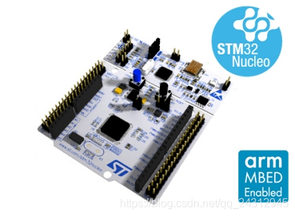
Flash就是淘宝上SPI接口的W25Q128模块。
选择芯片型号
使用STM32CUBEMX选择芯片stm32f030r8,如下所示:
配置时钟源
HSE与LSE分别为外部高速时钟和低速时钟,在本文中使用内置的时钟源,故都选择Disable选项,如下所示:
配置时钟树
STM32F0的最高主频到48M,所以配置48即可: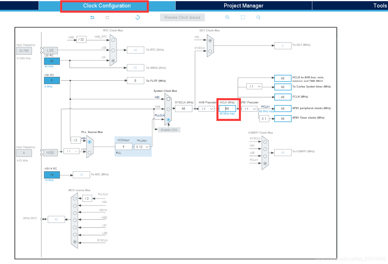
串口配置
本次实验使用的串口1进行串口通信,波特率配置为115200。
开启DMA。 中断。
中断。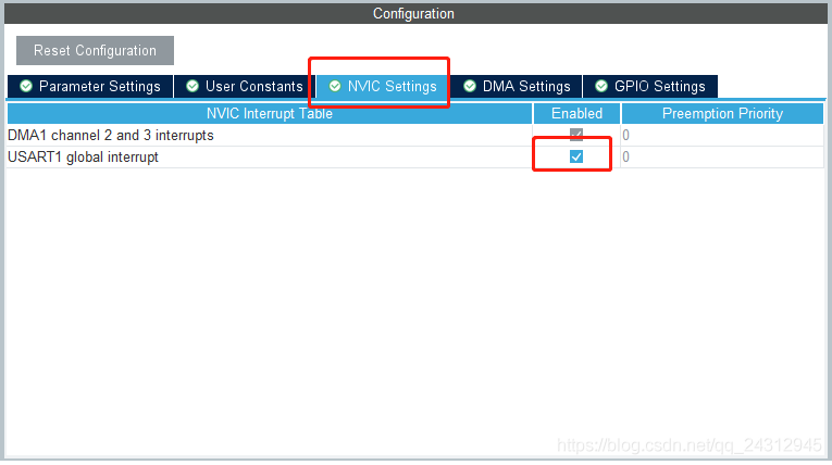
SPI配置
本次实验使用的SPI与Flash通信,配置如下。 SPI的通信原理很简单,它以主从方式工作,这种模式通常有一个主设备和一个或多个从设备,需要至少4根线,事实上3根也可以(单向传输时)。也是所有基于SPI的设备共有的,它们是MISO(主设备数据输入)、MOSI(主设备数据输出)、SCLK(时钟)、CS(片选)。 (1)MISO– Master Input Slave Output,主设备数据输入,从设备数据输出; (2)MOSI– Master Output Slave Input,主设备数据输出,从设备数据输入; (3)SCLK – Serial Clock,时钟信号,由主设备产生; (4)CS – Chip Select,从设备使能信号,由主设备控制。
接线方式
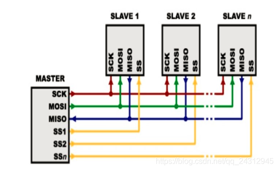
负责通讯的3根线了。通讯是通过数据交换完成的,这里先要知道SPI是串行通讯协议,也就是说数据是一位一位的传输的。这就是SCLK时钟线存在的原因,由SCLK提供时钟脉冲,SDI,SDO则基于此脉冲完成数据传输。数据输出通过 SDO线,数据在时钟上升沿或下降沿时改变,在紧接着的下降沿或上升沿被读取。完成一位数据传输,输入也使用同样原理。因此,至少需要8次时钟信号的改变(上沿和下沿为一次),才能完成8位数据的传输。 时钟信号线SCLK只能由主设备控制,从设备不能控制。同样,在一个基于SPI的设备中,至少有一个主设备。这样的传输方式有一个优点,在数据位的传输过程中可以暂停,也就是时钟的周期可以为不等宽,因为时钟线由主设备控制,当没有时钟跳变时,从设备不采集或传送数据。SPI还是一个数据交换协议:因为SPI的数据输入和输出线独立,所以允许同时完成数据的输入和输出。芯片集成的SPI串行同步时钟极性和相位可以通过寄存器配置,IO模拟的SPI串行同步时钟需要根据从设备支持的时钟极性和相位来通讯。 最后,SPI接口的一个缺点:没有指定的流控制,没有应答机制确认是否接收到数据。 其中,CS是从芯片是否被主芯片选中的控制信号,也就是说只有片选信号为预先规定的使能信号时(高电位或低电位),主芯片对此从芯片的操作才有效。这就使在同一条总线上连接多个SPI设备成为可能。 随便配置一个端口为CS片选,并且命名为CS。
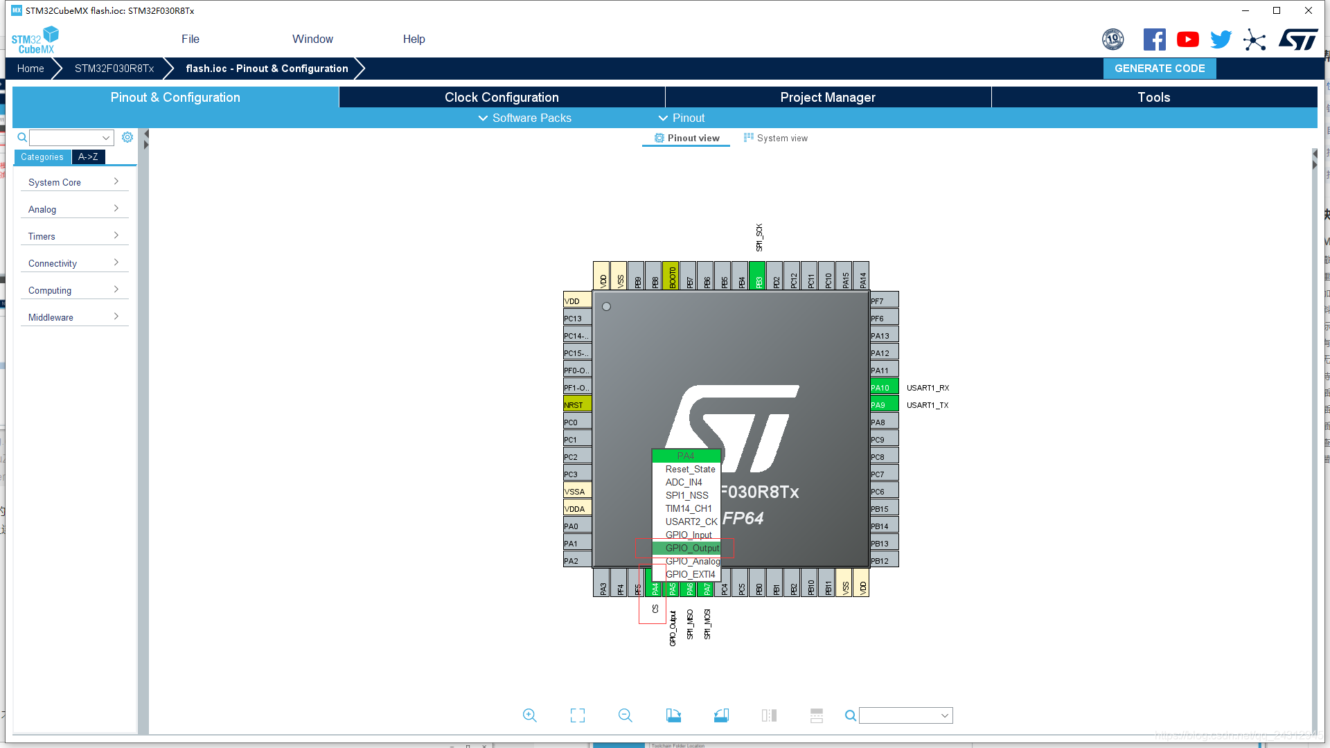
生成工程设置
注意在生产工程设置中不能出现中文,不然会报错。
生成代码
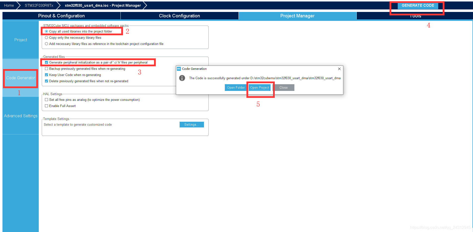
配置keil

W25Q128的原理及应用
W25Q128将16M的容量分为256个块(Block),每个块大小为64K字节,每个块又分为16个扇区(Sector),每个扇区4K个字节。 W25Q128的最小擦除单位为一个扇区,也就是每次必须擦除4K个字节 。 芯片ID如下所示。
0XEF13,表示芯片型号为W25Q80
0XEF14,表示芯片型号为W25Q16
0XEF15,表示芯片型号为W25Q32
0XEF16,表示芯片型号为W25Q64
0XEF17,表示芯片型号为W25Q128
驱动代码
W25Qx.c
/*********************************************************************************************************
*
* File : ws_W25Qx.c
* Hardware Environment:
* Build Environment : RealView MDK-ARM Version: 4.20
* Version : V1.0
* By :
*
* (c) Copyright 2005-2011, WaveShare
* http://www.waveshare.net
* All Rights Reserved
*
*********************************************************************************************************/
#include "W25Qx.h"
/**
* @brief Initializes the W25Q128FV interface.
* @retval None
*/
uint8_t BSP_W25Qx_Init(void)
{
/* Reset W25Qxxx */
BSP_W25Qx_Reset();
return BSP_W25Qx_GetStatus();
}
/**
* @brief This function reset the W25Qx.
* @retval None
*/
static void BSP_W25Qx_Reset(void)
{
uint8_t cmd[2] = {RESET_ENABLE_CMD,RESET_MEMORY_CMD};
W25Qx_Enable();
/* Send the reset command */
HAL_SPI_Transmit(&hspi1, cmd, 2, W25Qx_TIMEOUT_VALUE);
W25Qx_Disable();
}
/**
* @brief Reads current status of the W25Q128FV.
* @retval W25Q128FV memory status
*/
static uint8_t BSP_W25Qx_GetStatus(void)
{
uint8_t cmd[] = {READ_STATUS_REG1_CMD};
uint8_t status;
W25Qx_Enable();
/* Send the read status command */
HAL_SPI_Transmit(&hspi1, cmd, 1, W25Qx_TIMEOUT_VALUE);
/* Reception of the data */
HAL_SPI_Receive(&hspi1,&status, 1, W25Qx_TIMEOUT_VALUE);
W25Qx_Disable();
/* Check the value of the register */
if((status & W25Q128FV_FSR_BUSY) != 0)
{
return W25Qx_BUSY;
}
else
{
return W25Qx_OK;
}
}
/**
* @brief This function send a Write Enable and wait it is effective.
* @retval None
*/
uint8_t BSP_W25Qx_WriteEnable(void)
{
uint8_t cmd[] = {WRITE_ENABLE_CMD};
uint32_t tickstart = HAL_GetTick();
/*Select the FLASH: Chip Select low */
W25Qx_Enable();
/* Send the read ID command */
HAL_SPI_Transmit(&hspi1, cmd, 1, W25Qx_TIMEOUT_VALUE);
/*Deselect the FLASH: Chip Select high */
W25Qx_Disable();
/* Wait the end of Flash writing */
while(BSP_W25Qx_GetStatus() == W25Qx_BUSY);
{
/* Check for the Timeout */
if((HAL_GetTick() - tickstart) > W25Qx_TIMEOUT_VALUE)
{
return W25Qx_TIMEOUT;
}
}
return W25Qx_OK;
}
/**
* @brief Read Manufacture/Device ID.
* @param return value address
* @retval None
*/
void BSP_W25Qx_Read_ID(uint8_t *ID)
{
uint8_t cmd[4] = {READ_ID_CMD,0x00,0x00,0x00};
W25Qx_Enable();
/* Send the read ID command */
HAL_SPI_Transmit(&hspi1, cmd, 4, W25Qx_TIMEOUT_VALUE);
/* Reception of the data */
HAL_SPI_Receive(&hspi1,ID, 2, W25Qx_TIMEOUT_VALUE);
W25Qx_Disable();
}
/**
* @brief Reads an amount of data from the QSPI memory.
* @param pData: Pointer to data to be read
* @param ReadAddr: Read start address
* @param Size: Size of data to read
* @retval QSPI memory status
*/
uint8_t BSP_W25Qx_Read(uint8_t* pData, uint32_t ReadAddr, uint32_t Size)
{
uint8_t cmd[4];
/* Configure the command */
cmd[0] = READ_CMD;
cmd[1] = (uint8_t)(ReadAddr >> 16);
cmd[2] = (uint8_t)(ReadAddr >> 8);
cmd[3] = (uint8_t)(ReadAddr);
W25Qx_Enable();
/* Send the read ID command */
HAL_SPI_Transmit(&hspi1, cmd, 4, W25Qx_TIMEOUT_VALUE);
/* Reception of the data */
if (HAL_SPI_Receive(&hspi1, pData,Size,W25Qx_TIMEOUT_VALUE) != HAL_OK)
{
return W25Qx_ERROR;
}
W25Qx_Disable();
return W25Qx_OK;
}
/**
* @brief Writes an amount of data to the QSPI memory.
* @param pData: Pointer to data to be written
* @param WriteAddr: Write start address
* @param Size: Size of data to write,No more than 256byte.
* @retval QSPI memory status
*/
uint8_t BSP_W25Qx_Write(uint8_t* pData, uint32_t WriteAddr, uint32_t Size)
{
uint8_t cmd[4];
uint32_t end_addr, current_size, current_addr;
uint32_t tickstart = HAL_GetTick();
/* Calculation of the size between the write address and the end of the page */
current_addr = 0;
while (current_addr <= WriteAddr)
{
current_addr += W25Q128FV_PAGE_SIZE;
}
current_size = current_addr - WriteAddr;
/* Check if the size of the data is less than the remaining place in the page */
if (current_size > Size)
{
current_size = Size;
}
/* Initialize the adress variables */
current_addr = WriteAddr;
end_addr = WriteAddr + Size;
/* Perform the write page by page */
do
{
/* Configure the command */
cmd[0] = PAGE_PROG_CMD;
cmd[1] = (uint8_t)(current_addr >> 16);
cmd[2] = (uint8_t)(current_addr >> 8);
cmd[3] = (uint8_t)(current_addr);
/* Enable write operations */
BSP_W25Qx_WriteEnable();
W25Qx_Enable();
/* Send the command */
if (HAL_SPI_Transmit(&hspi1,cmd, 4, W25Qx_TIMEOUT_VALUE) != HAL_OK)
{
return W25Qx_ERROR;
}
/* Transmission of the data */
if (HAL_SPI_Transmit(&hspi1, pData,current_size, W25Qx_TIMEOUT_VALUE) != HAL_OK)
{
return W25Qx_ERROR;
}
W25Qx_Disable();
/* Wait the end of Flash writing */
while(BSP_W25Qx_GetStatus() == W25Qx_BUSY);
{
/* Check for the Timeout */
if((HAL_GetTick() - tickstart) > W25Qx_TIMEOUT_VALUE)
{
return W25Qx_TIMEOUT;
}
}
/* Update the address and size variables for next page programming */
current_addr += current_size;
pData += current_size;
current_size = ((current_addr + W25Q128FV_PAGE_SIZE) > end_addr) ? (end_addr - current_addr) : W25Q128FV_PAGE_SIZE;
} while (current_addr < end_addr);
return W25Qx_OK;
}
/**
* @brief Erases the specified block of the QSPI memory.
* @param BlockAddress: Block address to erase
* @retval QSPI memory status
